Buying a Toyota Supra
I’m writing this page as a general reply to all people sending me emails asking advice when buying a Supra. A lot of people visiting my site do not have a Supra and can only dream of having one, currently. Well people, the dream is over, as second hand Supra’s are getting way more cheaper. There are however some things you have to take in consideration when buying this awesome car. Here are the following things explained:
Service history
Check if the seller can show a service history. See what has been done on the car in the whole period of time and see if the car has had some big repairs recently. Maybe this is the reason the seller wants to get rid of the Supra. Ask the seller why he wants to get rid of his Supra.
Check if the car has had some serious damage in the past. How is this fixed? Does it look ok? If you cannot judge for yourself, have someone judge it for you.
Has the car always been serviced by Toyota? Is the count of the odometer registered? In a lot of countries the car’s odometer is registered every time it’s taken for servicing. In Holland this is called the nationale autopas.
Outside check (exterior)
Check the whole car for rust and dents. Places where rust are common are on both the doors (lower part), in the hatch (trunk) where the rubbers are. Rear spoiler, all points where it bolts into the car. The side skirts (they are plastic, but behind is metal). Around the taillights can be rust as well. See if the car has been over sprayed. To check this, open the door and check if you can see any color difference. Check if you can see any color difference on the whole car. A re-spray can tell you the car has had damage.
Check the windows. Are all windows marked the same or is one window not the same as others. If a window is replaced the car might have been stolen, or again repaired.
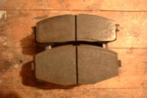
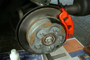
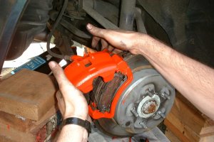
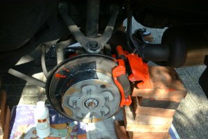
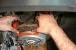
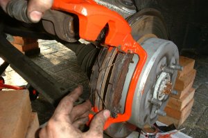
Check the wheels. Do the rims still look ok? How about the tires? Are they worn? New tires cost quite some money, so buying a car with good tires is not a bad thing. Can you see the brake discs? Do they look very worn or carved? Replacing brakes is not cheap either.
Check the taillights. Is there any water in the lights? Water is not a good thing. Open the trunk. Check the spare wheel. Has it been used a lot? A good spare wheel is never used of course. Check under the spare wheel, is there any water or rust in here? If you find this, the rubbers on the trunk or the taillights are worn. A lot of Supra’s have this problem.
Check the targa roof. Does it still keep the rain outside the vehicle? Maybe you can check this by checking the cloth in the car. Do you see any wet marks?
Interior
Move more into the car. How does the car look from the inside? Does the inside look the same as the mileage on the clock? If the car looks totally worn out and the clock is only showing 100.000 kilometers you might want to check if it has been tampered with.
Do all gages still work? Some cars had a bad oil pressure gauge. Do all interior lights work and how about the electronic windows and the filler cap opener?
Check the rest of the inside if everything looks ok.
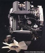
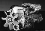
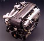
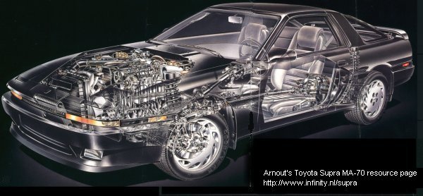
Engine checks
Open the hood and get a general impression of the engine bay. Check for oil and coolant leaks. Especially the valve covers are known for this. Oil leaks at the valve covers is not really bad, but it can show the maintenance of the engine is neglected.
Get the oil filler cap off. Check the state of the oil. If there is some white or gray cream in the cap, this might be a blown head gasket engine. The other possibility is the valve seals are worn. Ask the seller if he had any overheating problems with the car.
Check the color of the oil. The oil color can be best seen at the end of the dipstick, so take that one out as well. If the oil is very black, it hasn’t been changed in a long time. While having the dipstick in your hand see what the oil level is. Check the oil level for the automatic transmission as well. Check all other levels, like engine coolant level, power steering and brake fluid.
If possible check the condition of the Turbo. Do so by checking it’s the original turbo and not a replacement. Replacement turbo’s will have some scratches (or scratches on the exhaust manifold’s heat shield) because of the repair. If you got the time, get the accordion hose off the turbo and check the wheel play of the turbo’s turbine wheel. Check if the turbine wheel rotates without any (big) problem.
Test drive the car
Listen to the engine. In a good (stock) Supra you will hardly hear the engine. To check the engine sound open the windows and drive near some walls. Do this at both low and high speed & revs.
Accelerate to about 150 km/h if possible and hit the brakes as hard as you can. Check if the car stays in a straight line. If not, release the brakes immediately to prevent killing yourself. Better to do this test when you are prepared for doing it, than when you NEED to do it and find out the car will turn around or not continue in a straight line at least.
Check if the manual transmission shifts without any problem in all gears, take special tests for the 2nd gear and the reverse gear. If it’s hard to shift into these, the synchronization rings might be worn.
Check if the cruise control works without any problem.
Well, this is whatever comes at me first. When you got some tips yourself, please send them to me at arnout@supras.nl I’ll be happy to add them to this list. Whatever is wrong with the car, it must not prevent you from buying the car if it’s the right price. If you can buy a completely wrecked Supra for let’s say 200 bucks I would do so, the parts are always worth something. If you happen to buy a NA Supra for let’s say $ 7000, I would really reconsider this. When it’s a perfect car, you can do so as it might be a good deal, but well, it’s your own decision after all!